Electronics Project
2024-11-21 Back to posts
I love electronics, so when I had to pick a project from the list for this electronics class, I knew I wanted to tackle one of the hardest ones. For our final project, we chose to pick the one that required us to make a set of modular circuits that would allow the user to type a 30 character message and play it back on three 17 segment displays. The callenge was that we were not allowed to use any microcontrollers, meaning no arduino code, just digital logic ICs.
Design
I single handedly designed all the circuits for our project on a circuit simulation website called Falstad. This allowed me to be able to run through serveral iterations and to see immediate flaws in the design (there were many).
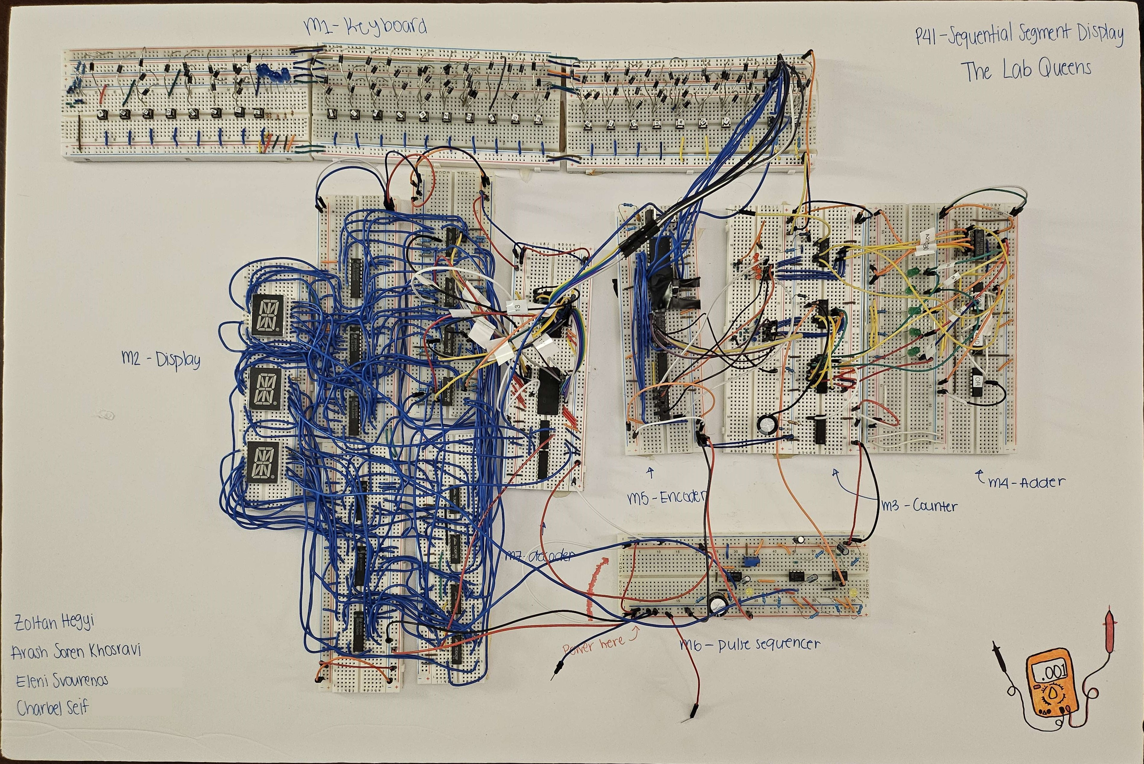
Without giving away too much (to avoid plagiarism by future student), the project consists of seven modules, each resposible for a specific task:
-
The Keyboard which is a series of push buttons each with a unique 5 bit binary connection to the Address bus
-
The three 17 segment displays with a series of D-latches to store the letter of the adjacent display before it in turn changes and stores the letter of the first display which is connected to module 7
-
The Counter, consisting of two binary counters, serves two purposes: A. to keep track of the position in memory when writting to the Encoder EEPROM as well as to B. cycle through all the letters when playing back the message.
-
The Adder is used to take the count from the first counter corresponding to the number of letters typed and adding 2 so that when the message is read back there are two spaces before it loops back to the first character. This is done using a magnitude comparator IC such that when reading back the message, the second counter will keep counting up indefinitely until it counts to the value of the first counter plus two and then get reset by the comparator.
-
The Encoder is a single EEPROM which saves the 5 bit binary word associated to each letter of the alphabet.
-
The Pulse Sequencer is the beating heart of the whole project. It is the clock that is responsible for advancing everything. It consists of three 555 timer chips. The first is configured as an Astable 555 circuit acting as the clock; it is connected to the second set of D-Latches and triggers the third display to copy the second. The second and third chips are configured as monostable circuits, creating a pulse on the falling edge of the previous pulse. the first monostable 555 gets triggered by the astable 555 and is connected to the first set of D-Latches which triggers the second display to copy the first. The second monostable 555 (the third 555) is connected to the clock in module 3 to advance the count and display the next letter.
-
The Decoder, two EEPROMs preprogrammed by a member of the team where every binary address corresponds to a series of LEDs that need to be lit to form a letter. In other words, every address corresponds to a letter. This address comes from the Encoder.
If any of that sounded confusing it is because it is. Comming up with this final design took a lot of work and a bit of trial and error. After several iterations, this is what I could come up with given the time.
Construction
The construction had to be the most tedious part of the project, which is why I am very fortunate to have had a group of very hard working teammates that really came through to get this project functioning by the deadline.
The mess of wires around the displays took four tries before it was wired correctly, requiring a full spool of insulated wire (initially we tried with just jumper wires but they were too unreliable).
The Adder was constructed manually by a fellow teammate out of AND/OR gates as we couldn’t find a 5 bit adder in time.
The Keyboard was painstakingly assembled one push button at a time by another fellow teammate requiring roughly 80 diodes.
In the end, we managed to assemble and test everything in the nick of time and finished just mere moments before the 2024 North American Solar Eclipse, after which we drove straight to school to present.
Further documentation for the project including schematics and detailed pictures of every module will be released in the future at the professors discretion.